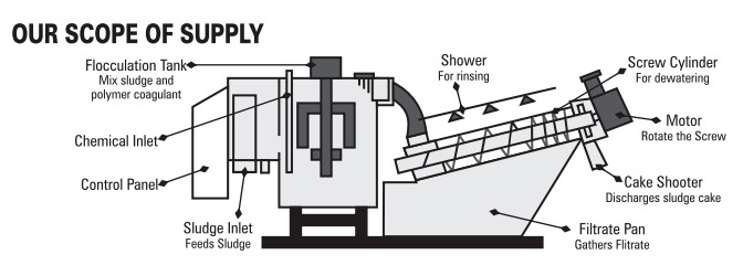
The combo-sludge dewatering system consists of a flocculation tank equipped with an agitator and a screw press for dewatering sludge.
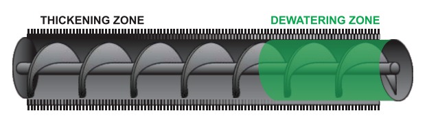
The dewatering system has a cylinder that encloses the rotating screw. The cylinder is constructed by fixing alternate placements of fixed rings, moving rings, and spacers. The screw rotating inside the cylinder has two operating zones: the first zone is known as the thickening zone and the second zone is known as the dewatering zone.
WORKING PRINCIPAL
The sludge enters the combo dewatering machine and the sludge moves towards the sludge cake outlet under pressure from the helical screw blades. Since the pitch becomes narrower towards the outlet of the sludge cake, the sludge bears heavier pressure and begins to dewater. Water comes out from the space between fixed and moving rings while dry solids exits from the outlet.
ADVANTAGES
APPLICATIONS
| S.No. | Description | Combo Dewatering Machine | Decanter Centrifuge |
| 1 | Opreation | Continuous | Continous |
| 2 | Power | Quite Less for example for 3m/hr the power required is (0.75 HP) | More (for similar flow of Sludge power required is 12.5HP or More) |
| 3 | RPM | 3 - 4 | More than 3500 |
| 4 | Noise | Very Low | Very High |
| 5 | Maintenance | Low & Easy | High & Touch |
| 6 | Low Concentration Sludge | Very Good | Good |
| 7 | Oily Sludge | Very Good | Not so Good |
| S. No. | Model No. | Flow Rate @ 1% Solid Concentration M3/Hr | Cylinder Specification (mm) | Power Consumption (HP) | Dimension L*W*H(MM) |
Rinsing Water (L/hr) |
| 1 | WV - 5.5 | 0.3 | 1*55 | 0.5 | 1100*750*550 | 20 |
| 2 | WV - 7.5 | 0.5 | 1*75 | 0.5 | 1200*750*1000 | 20 |
| 3 | WV - 9.5 | 1 | 1*97 | 0.5 | 1800*710*1100 | 30 |
| 4 | WV - A10 | 1.5 | 1*110 | 0.5 | 2100*750*1100 | 30 |
| 5 | WV - 2A10 | 3 | 2*110 | 0.75 | 2100*1050*1100 | 60 |
| 6 | WV- 3A10 | 4.5 | 3*110 | 0.75 | 2100*1400*1100 | 40 |
| 7 | WV - B10 | 6 | 1*210 | 0.75 | 3050*900*1800 | 80 |
| 8 | WV - 2B10 | 12 | 2*210 | 1.25 | 3050*1400*1800 | 80 |
| 9 | WV - B50 | 9 | 1*250 | 1 | 3400*1000*2100 | 100 |
| 10 | WV - 2B50 | 18 | 2*250 | 1.75 | 3400*1550*2100 | 200 |
| 11 | WV - C50 | 25 | 1*350 | 2 | 4100*1100*2200 | 200 |
| 12 | WV - 2C50 | 50 | 2*350 | 3.5 | 4100*1600*2200 | 300 |
| 13 | WV - 3C50 | 75 | 3*350 | 5 | 4100*2100*2000 | 450 |